DC Circuits
CSCA DC Circuits study guide organized around the publicly available CSCA syllabus. Practice Physics questions on aicsca.com.
Before planning this topic, check the CSCA Exam Guide 2026 for exam dates, registration, fees, and subject requirements.
Syllabus Alignment
This study guide is organized around the publicly available CSCA syllabus for international undergraduate applicants.
Who It Is For
International students preparing for CSCA Math, Physics, Chemistry, or Chinese exams.
Related Practice
CSCA Practice · Go to questions
Past papers and worked video solutions · Timed mock exams · All subject video lessons
Practice by Topic
Jump from this tutorial to filtered practice questions for the same knowledge point.
Related formulas, concepts, and glossary terms
Physics Formula & Concept Reference
- Total Resistance in Series Circuit
- Current Divider Formula in Parallel Circuit
- Total Voltage in Series Circuit
- Total Resistance in Parallel Circuit
- Voltage Divider Formula in Series Circuit
- Total Current in Parallel Circuit
- What is the formula of Ohm's Law?
- Ohm's Law (for a complete circuit)
Physics Exam Glossary
Tutorial Content
Topic: Electromagnetism > DC Circuits
1. Introduction: Direct Current (DC) Circuits
A **DC Circuit** is a circuit where the direction of the current does not change with time. This is the foundation for analyzing more complex circuits (like AC circuits) and understanding electronic devices.
For the CSCA exam, you need to master these core elements:
* **Power Source (EMF)**: Provides a constant voltage (potential difference) to drive charge flow.
* **Load (Resistor)**: Consumes electrical energy.
* **Wires & Switches**: For connection and control.
---
2. Core Quantities and Laws
| Quantity/Law | Symbol | Definition/Formula | Unit | Notes |
| :--- | :---: | :--- | :---: | :--- |
| **Current** | $I$ | $I = \frac{Q}{t}$ (Charge flow per unit time) | **Ampere (A)** | Direction is the flow of **positive** charge. Outside source: Positive $\to$ Negative |
| **Voltage** | $U$ | $U_{AB} = V_A - V_B$ (Potential difference) | **Volt (V)** | The driving force for current |
| **Resistance** | $R$ | $R = \frac{U}{I}$ (Definition)<br>$R = \rho \frac{L}{S}$ (Determination) | **Ohm ($\Omega$)** | Opposition to current flow |
| **Ohm's Law** | - | **$I = \frac{U}{R}$** | - | **Core Law**. Applies ONLY to **Pure Resistive Components** (converts all electrical energy to heat, e.g., heaters, incandescent bulbs) |
**CSCA Exam Warning**:
NEVER directly apply $I=U/R$ to calculate the total current or voltage of a non-pure resistive circuit containing **motors** (electrical $\to$ mechanical + heat) or **charging batteries** (electrical $\to$ chemical + heat).
---
3. Core Models: Series and Parallel
Identifying series and parallel connections is the first step in solving problems. The key is to look at the **current path**.
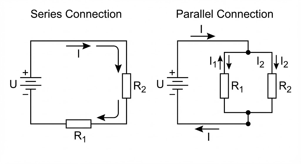
| Feature | Series Circuit | Parallel Circuit |
| :--- | :--- | :--- |
| **Connection** | Connected end-to-end, **ONLY ONE** path for current. | Heads connected together, tails connected together, **MULTIPLE** branch paths. |
| **Current Rule** | Same everywhere: $I = I_1 = I_2$ | Total equals sum of branches: $I_{total} = I_1 + I_2$ |
| **Voltage Rule** | Total equals sum of individual voltages: $U_{total} = U_1 + U_2$ | Voltage across each branch is equal: $U = U_1 = U_2$ |
| **Equivalent R** | **Increases with more resistors**: $R_{eq} = R_1 + R_2$ | **Decreases with more resistors**: $\frac{1}{R_{eq}} = \frac{1}{R_1} + \frac{1}{R_2}$ |
| **Divider Rule** | **Voltage Divider (Proportional)**: $\frac{U_1}{U_2} = \frac{R_1}{R_2}$ | **Current Divider (Inverse)**: $\frac{I_1}{I_2} = \frac{R_2}{R_1}$ |
---
4. Standard Problem-Solving Steps
1. **Identify Structure**: Determine if it's series, parallel, or mixed. Draw an equivalent circuit if necessary. Treat ideal ammeters as wires and voltmeters as open circuits.
2. **Label Knowns**: Mark known $U, I, R$ values on the diagram.
3. **Apply Laws Flexibly**:
* First, use general series/parallel rules (like total resistance, total current).
* Then, use Ohm's Law $U=IR$ for individual components.
4. **Energy Analysis (if needed)**: Power $P = UI$. For pure resistors, $P = I^2R = U^2/R$.
---
5. Typical Examples
**Example 1: Basic Series Circuit**
**Problem**: As shown, source voltage $U = 12V$, resistors $R_1 = 4\Omega$ and $R_2 = 8\Omega$ are in series. Find: (1) Total resistance; (2) Current; (3) Voltage across $R_1$.
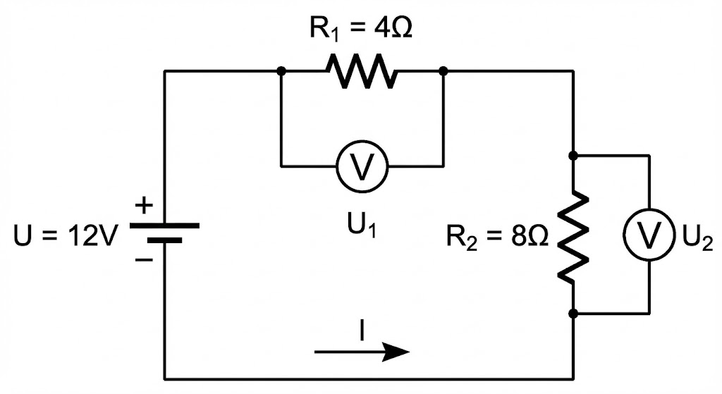
**Solution**:
1. **Total R** (Sum): $R_{eq} = R_1 + R_2 = 4 + 8 = 12\Omega$
2. **Total I** (Ohm's Law): $I = \frac{U}{R_{eq}} = \frac{12}{12} = 1A$
3. **Voltage of $R_1$** (Partial Ohm's Law): $U_1 = I \cdot R_1 = 1A \times 4\Omega = 4V$
**Example 2: Basic Parallel Circuit**
**Problem**: As shown, source voltage $U = 24V$, resistors $R_1 = 6\Omega$ and $R_2 = 12\Omega$ are in parallel. Find: (1) Total resistance; (2) Total current; (3) Current through $R_2$.
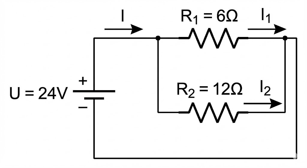
**Solution**:
1. **Total R** (Sum of reciprocals): $\frac{1}{R_{eq}} = \frac{1}{R_1} + \frac{1}{R_2} = \frac{1}{6} + \frac{1}{12} = \frac{3}{12} = \frac{1}{4} \Rightarrow R_{eq} = 4\Omega$
**Tip**: For two parallel resistors, use $R_{eq} = \frac{R_1 R_2}{R_1 + R_2}$ for faster calculation.
2. **Total I**: $I_{total} = \frac{U}{R_{eq}} = \frac{24}{4} = 6A$
3. **Current in $R_2$** (Voltages are equal): $I_2 = \frac{U}{R_2} = \frac{24}{12} = 2A$
**Example 3: Simple Mixed Circuit**
**Problem**: As shown, $U = 12V$, $R_1 = 3\Omega$, $R_2 = R_3 = 6\Omega$. $R_2$ and $R_3$ are in parallel, and this combination is in series with $R_1$. Find the current through $R_1$ and the voltage across $R_2$.
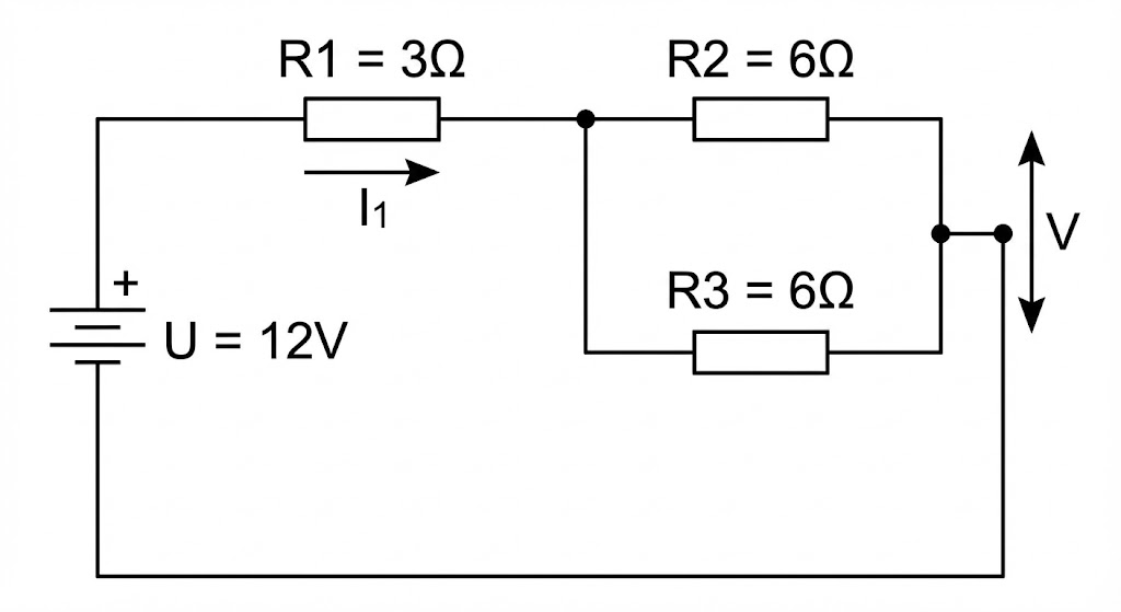
**Solution**:
**Strategy: Solve the parallel part first, then the overall series circuit.**
1. **Parallel Part**: Resistance of $R_2, R_3$ in parallel ($R_{23}$).
$R_{23} = \frac{R_2 R_3}{R_2 + R_3} = \frac{6 \times 6}{6 + 6} = 3\Omega$
2. **Total Resistance**: $R_1$ in series with $R_{23}$.
$R_{total} = R_1 + R_{23} = 3 + 3 = 6\Omega$
3. **Total Current** (Current through $R_1$):
$I_1 = I_{total} = \frac{U}{R_{total}} = \frac{12}{6} = 2A$
4. **Voltage across $R_2$**: This is the voltage across the parallel combination $R_{23}$ ($U_{23}$).
Method 1 (Voltage Division): $U_{23} = U - U_1 = U - I_1 R_1 = 12 - (2 \times 3) = 6V$.
Method 2 (Ohm's Law): $U_{23} = I_{total} \cdot R_{23} = 2A \times 3\Omega = 6V$.
Therefore, the voltage across $R_2$ is $U_2 = U_{23} = 6V$.
---
6. CSCA Common Pitfalls
1. **Matching Variables**: When using $U=IR$, make sure $U, I, R$ all belong to the **same component** or the **same section** of the circuit.
2. **Parallel R Calculation**: Don't forget to take the reciprocal at the end! For $n$ identical resistors $R$ in parallel, total R is $R/n$.
3. **Circuit States**:
* **Short Circuit**: A direct wire connection between two points. Resistance approaches zero, current becomes huge.
* **Open Circuit**: A break in the circuit. Resistance approaches infinity, current is zero.
4. **Meter Models**: When analyzing circuit structure, treat ideal **ammeters as wires** and ideal **voltmeters as open circuits** to simplify.